INTEGRAL®
Comprehensive solution for protecting small sites
All-in-one solution for comprehensive low-voltage installation protection. The INTEGRAL® range is the solution to electrical issues in small and medium installations, featuring highly sensitive equipment, such as bank branches, medical offices, medical analysis laboratories, etc. It improves the continuity of electrical service, preserves installed equipment, including inverters, and enhances their lifespan.
Description
Several breakdowns regularly affect the equipment installed in sites connected to the low-voltage network of electricity distributors: bank branches, medical offices, laboratories, office buildings, small telecom or broadcasting sites, etc., causing service interruption or even the destruction of sensitive equipment such as ATMs, medical equipment, transmitters, PCs, and LED lighting.
Even the installation of double-conversion online uninterruptible power supplies does not solve the majority of these problems. Worse, UPS units are among the first to suffer from these phenomena.
Applications :
These disturbances often originate from external sources but can also be internal in some cases. They can come from:
All-in-one solution for comprehensive protection of low-voltage installations
MEIER ENERGY offers the INTEGRAL® range, a unique solution on the market, designed to comprehensively protect low-voltage electrical installations for professional subscribers.
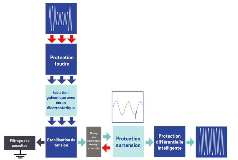
Very easy to install and use, this plug-and-play solution, based on static voltage regulator-stabilizers equipped with protections against transient surges, permanent surges, neutral disconnections, voltage dips, ground leakage currents, also ensures protection against third-order harmonics and earth leakage currents. It helps preserve electronic equipment and optimize their lifespan, while bringing substantial energy savings in the majority of cases.
Main features:
Easy installation:
Other optional features:
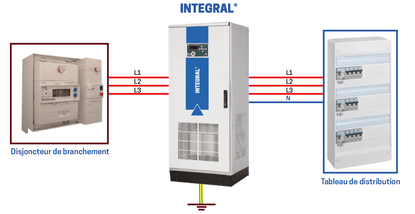
The insertion of the INTEGRAL® voltage stabilizer-regulator into the existing installation is quick and easy. Simply insert it between the main circuit breaker of the site (or the one at the point of protection) and the low-voltage main switchboard of the site (or the electrical panel of the section to be protected).
Grounding can be done directly on the existing mass earth network or with the help of a dedicated new earth pit.

Technical specifications:
| General features | |||
|---|---|---|---|
| Power (kVA) | Power range from 3kVA to 250kVA (other powers available on request) | .||
| Technology | Thyristor Technology, fast voltage regulation, maintenance-free design | ||
| Thyristor Configuration | 6 Thyristors | 8 Thyristors | 10 Thyristors |
| Inputs | |||||||
|---|---|---|---|---|---|---|---|
| Nominal input voltage | Model three-phase: 400V AC three-phase + Neutral + Ground (without neutral) | Model single-phase: 230V AC single-phase + Neutral + Ground | |||||
| (Different voltages are available as an option) | |||||||
| Voltage tolerance | Model S : -25%,+15% | Model M : -35%,+15% | Model L : -50%, +15% | ||||
| Frequency | 50Hz +/-5% (60Hz optional) | ||||||
| Outputs | |||||||
|---|---|---|---|---|---|---|---|
| Nominal output voltage | Three-phase model: 400V AC three-phase + Neutral + Ground | Model single-phase: 230V AC single-phase + Neutral + Ground | |||||
| (Different voltages are available as an option) | |||||||
| Voltage tolerance | +/-1% to +/-3% depending on the model | ||||||
| Frequency | 50Hz +/-5% | ||||||
| Overload capacity | 125% 1min. 150% 10sec. 151% and above 0.2 sec | ||||||
| Response time | 20msec | ||||||
| Correction time | 100msec - 200msec | ||||||
| Efficiency | ≥ 93% typical | ||||||
| Management, control, and communication interfaces | ||||||
|---|---|---|---|---|---|---|
| Control panel with LCD display | LCD display 4x20 and synoptic diagram Input voltage, output voltage, Load percentage, Frequency, Information and error status, installation parameters |
|||||
| Remote management interface (optional) | Remote management via browser with Ethernet connection (optional) Modbus RTU with RS485 connection (optional) |
|||||
| Protection functions | ||||||
|---|---|---|---|---|---|---|
| Voltage protection | Electronic protection for low voltage and high voltage | |||||
| Current protection | Magnetic-thermal circuit breaker at input and output | |||||
| Overload protection | Electronic overload protection (1min. at 125% overload, 10sec. at 150% overload, 0.2sec. at overload >151%) | |||||
| Overheating protection | Electronic protection against overheating (the fan starts at 50°C. The load power is cut off at 80°C.) | |||||
| Surge arrester | Surge arrester Class-I and Class-II | |||||
| Environmental conditions | ||||||
|---|---|---|---|---|---|---|
| Operating temperature | -10°C ~+50°C | |||||
| Operating altitude | 1.500m | |||||
| Humidity | 90% non-condensing | |||||
| Acoustic noise | 55dB (at a distance of one meter with closed door) | |||||
| Cabinet features | ||||||
|---|---|---|---|---|---|---|
| Type - Protection class | Interior type IP21: Free-standing modular cabinet. Exterior types IP54 or IP66 (optional). |
|||||
| Paint - Color | Epoxy-Polyester powder coating - RAL 7035 | |||||
| Cooling | Forced air cooling with fan controlled by thermostat | |||||
Product Documentations
- Dépliant Integral Download


