

Description
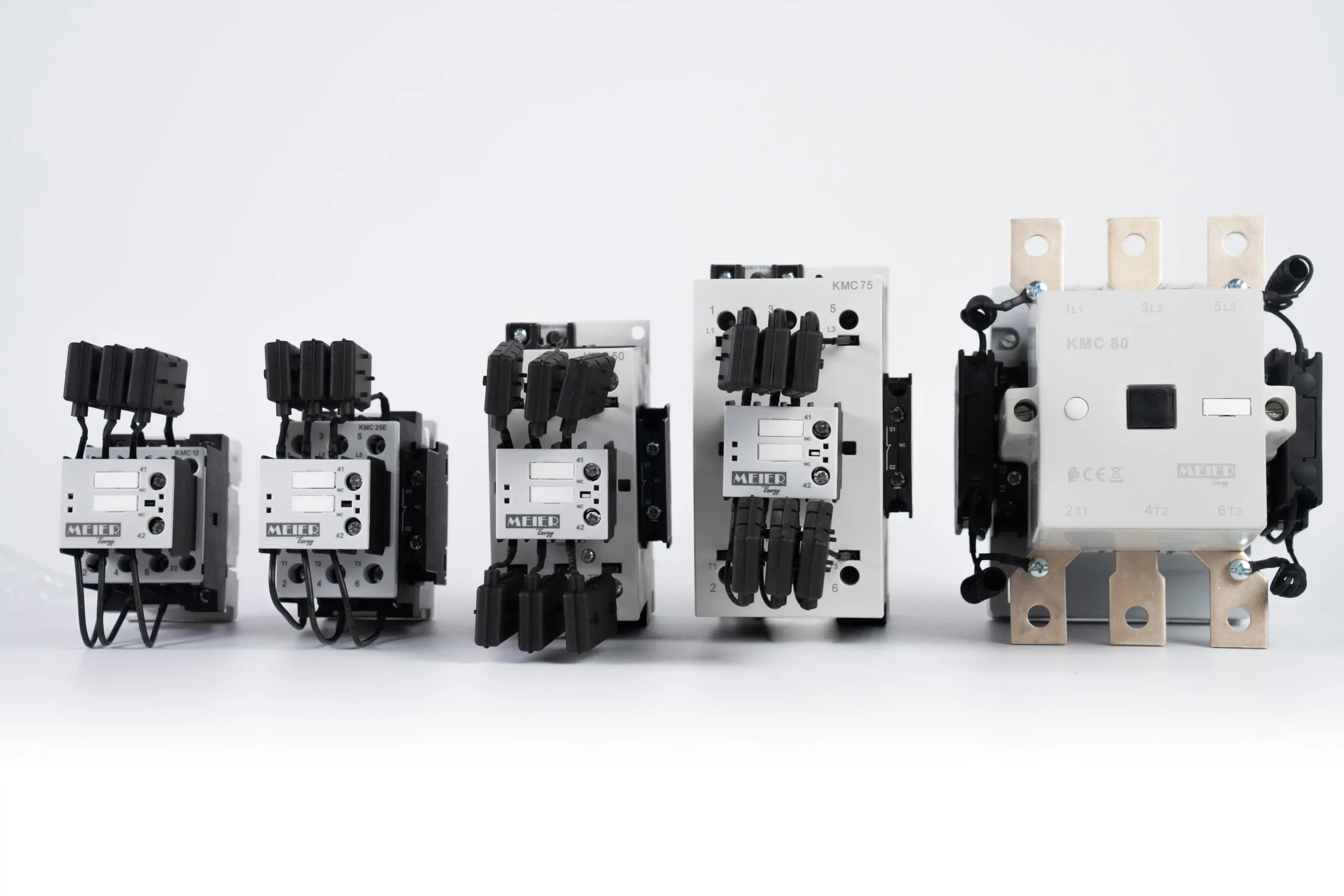
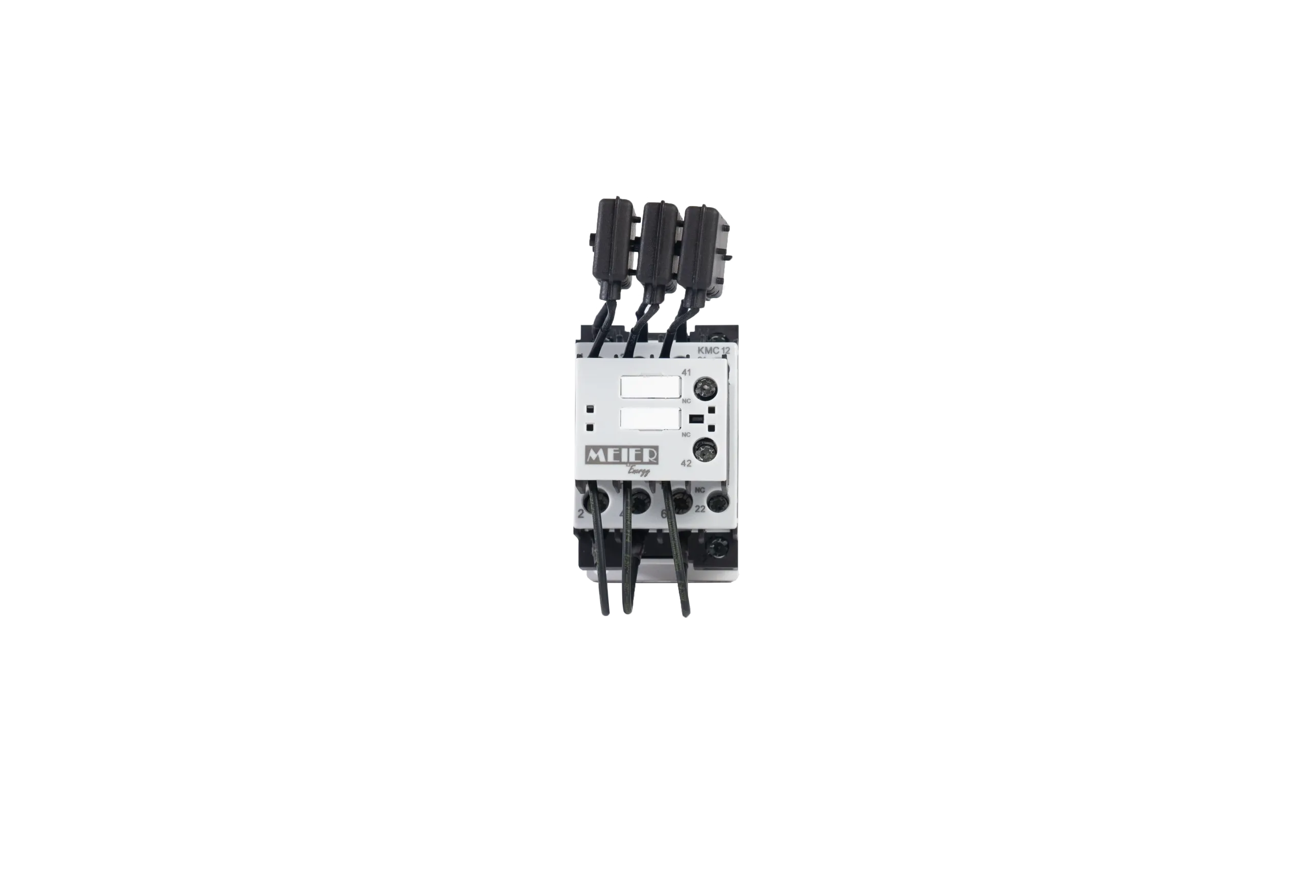
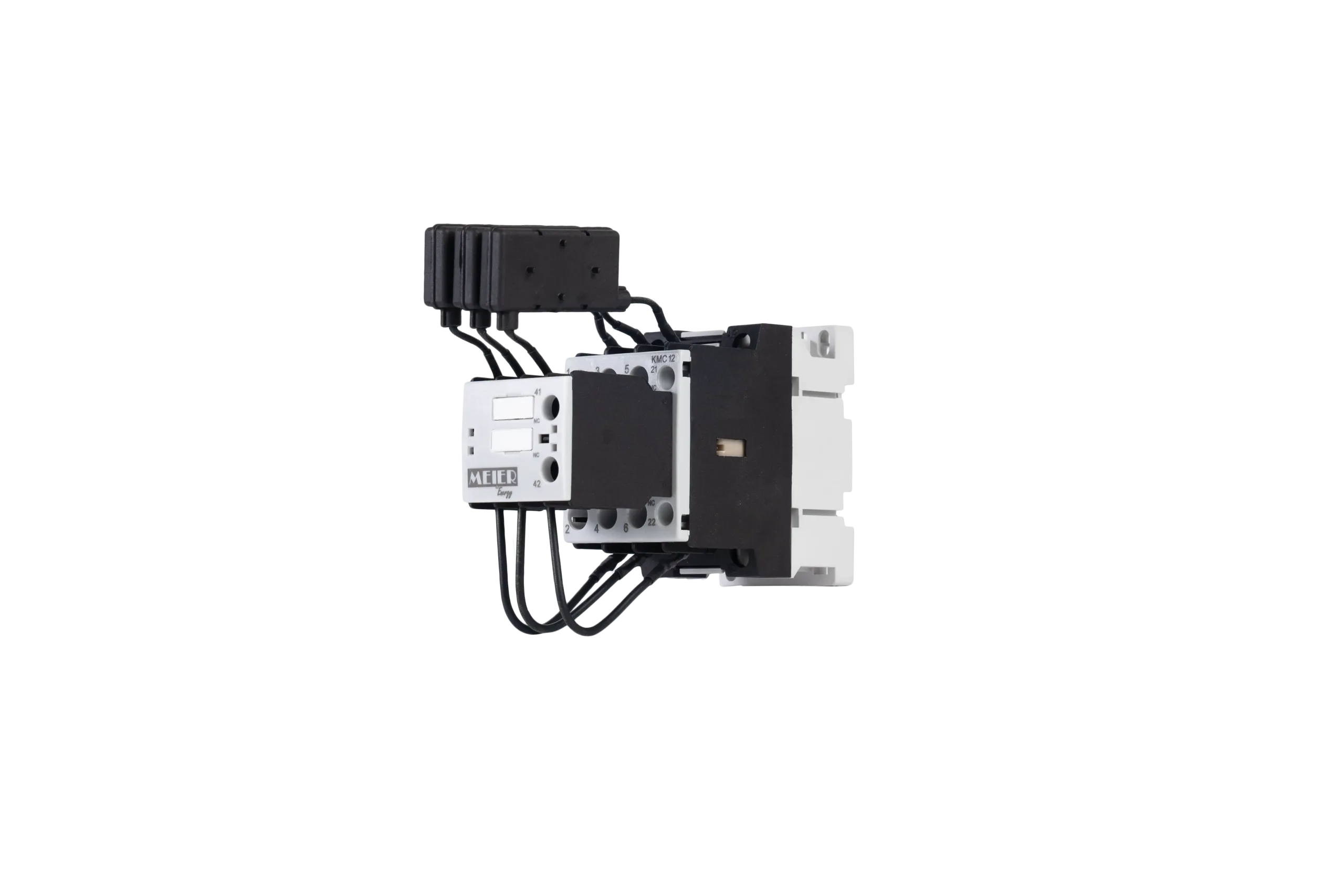
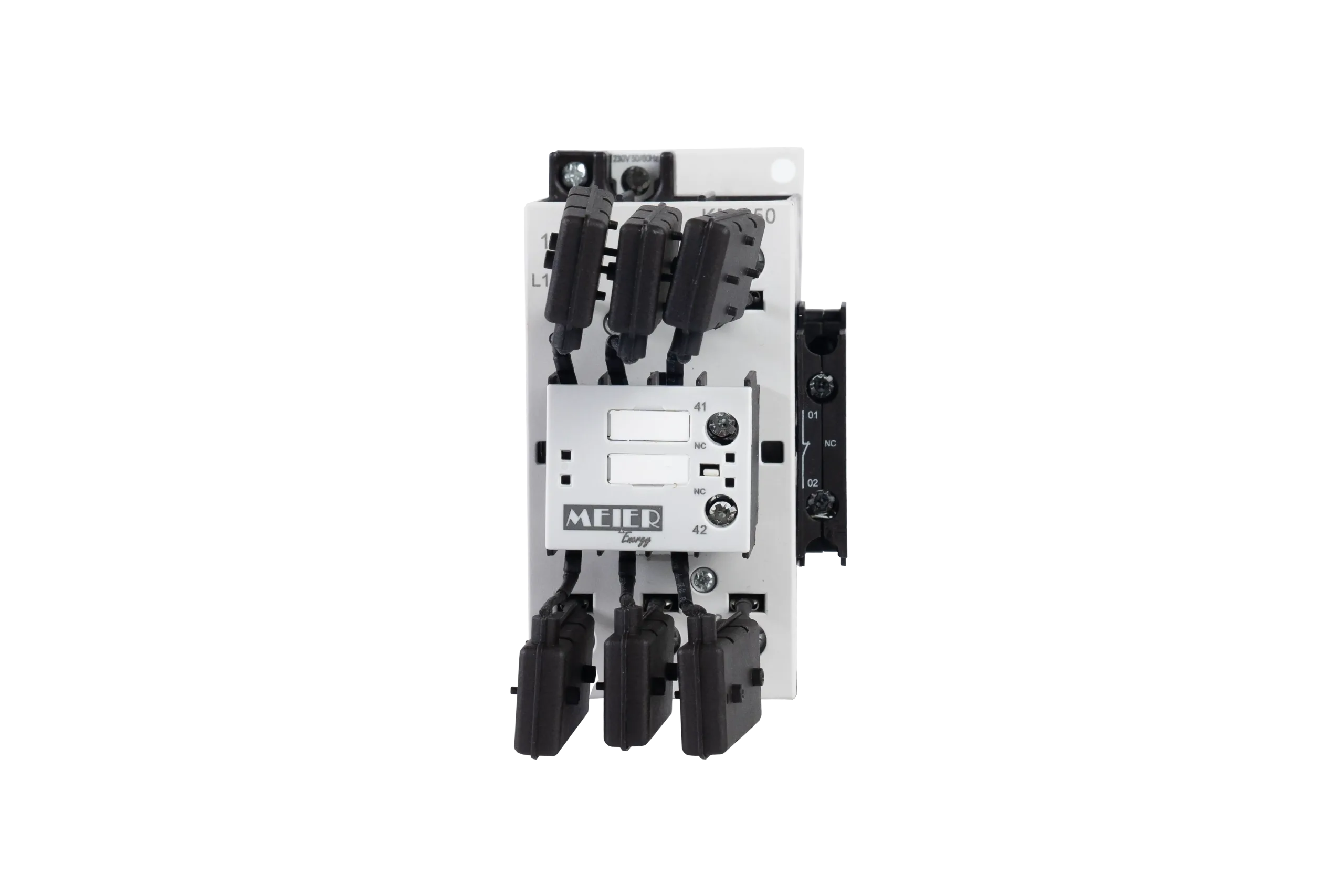
The KMC series contactors are used for the automatic control of three-phase capacitor banks with a rated power of 5 kVAR to 75 kVAR (230V to 690V / 50 Hz).
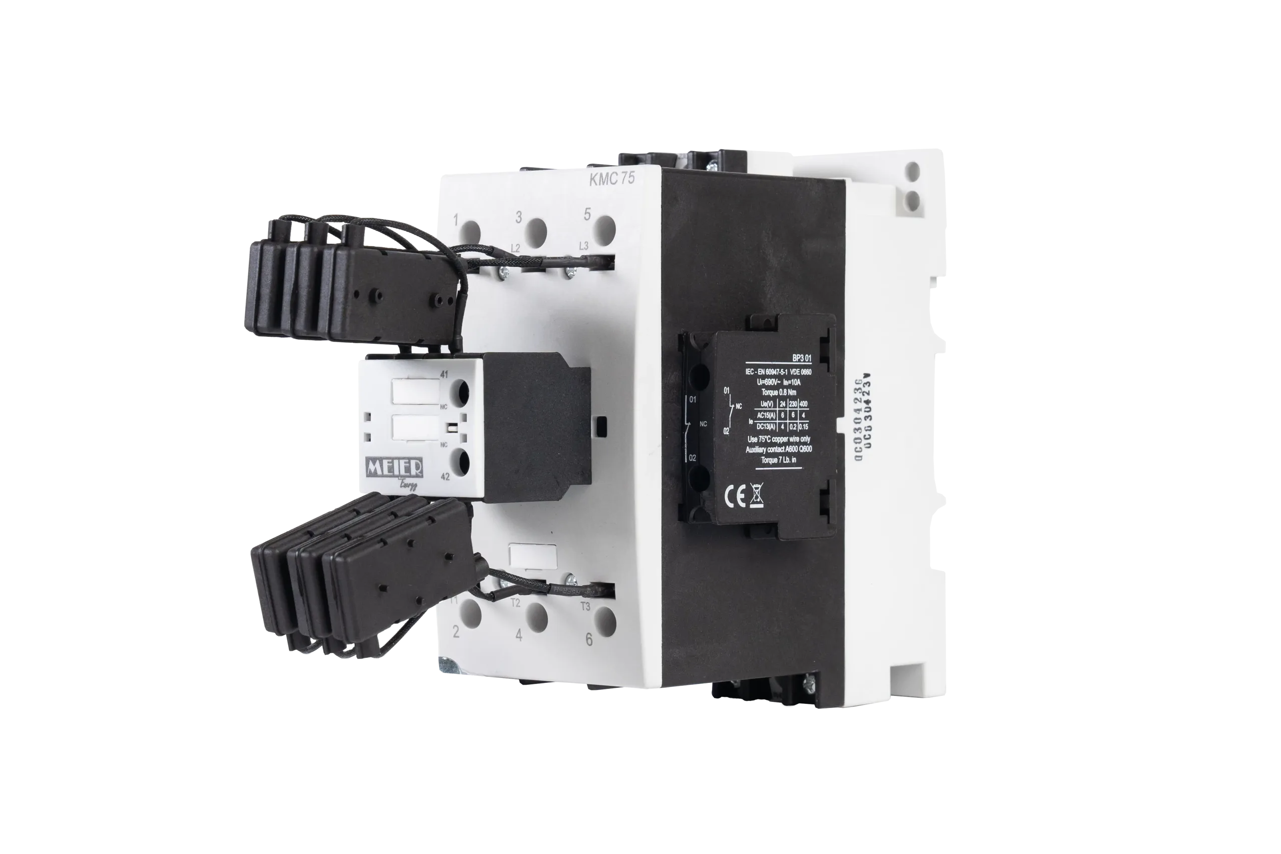
They are equipped with pre-charge resistors connected via early-closing contacts, which are an integral part of the KMC contactors.
This particular type of contacts is designed to connect resistors for a very short time, up to 5ms, during the closing of the contactor, limiting the inrush current of the capacitors. These resistors are then bypassed once the closing operation is completed, and the current capacity is transferred to the main contacts. This type of circuit allows for minor wear on all system components, including fuses and capacitors, ensuring a longer lifespan and improved reliability. Suitable for capacitors with and without anti-harmonic reactors.
Technical sheet
| Designation | Type | KMC12 | KMC25 | KMC50 | KMC75 | |
|---|---|---|---|---|---|---|
| Capacitor power at rated voltage 50/60Hz | 230V 400-440V 500-550V 660-690V |
/kvar /kvar /kvar /kvar |
6.7 12.5 15 18 |
14 25 30 35 |
29 50 60 70 |
38 75 80 105 |
| Rated operational current Ie/AC-6b at 400V | A | 18 | 36 | 72 | 108 | |
| Rated operational current Ith at 400V | A | 25 | 50 | 100 | 150 | |
| Isolation voltage Ui | V | 690 | 1000 | |||
| Operating ambient temperature | °C | de -25 à +55 | ||||
| Impulse withstand voltage Uimp | kV | 8 | ||||
| Coil power consumption at cold state | When switching on f.p. Triggered f.p. |
VA VA VA VA |
62 0,75 7 0,3 |
65 0,75 8 0,3 |
155 0,6 12 0,29 |
204 0,54 16 0,26 |
| Coil | Voltage tolerances Tightening torque Clamping screw type |
Nm | 0,85 – 1,1 UN 0,8 M3,5/PZ2 |
|||
| Degree of protection | IP 20 | |||||
| Maximum fuse rating | Main circuit gL/gG Auxiliary circuit |
A A |
35 16 |
63 16 |
125 16 |
160 16 |
| Frequency of switching operations | c/h | 240 | 120 | 100 | 100 | |
| Electrical endurance | min | 250.000 | 125.000 | 100.000 | ||
| Conductor dimensions (Power circuit) |
Multi-wire cable
Clamping screw |
mm2 | 1.5-6
M4 |
2.5-10
M4 |
16-35
M6 |
25-50
M8 4 – 4.5 Nm |
| Conductor dimensions (Control circuit) |
Multi-wire cable Clamping screw Screw head type Tightening torque |
mm2 mm2 |
1-2,5 0,75-1,5 M3,5 |
|||
| Maximum load of auxiliary contacts – Current at 35°C | A | 10 | 16 | |||
| Rated AC operational current Ie/AC15 under: | 230V 400V 500V 690V |
A A A A |
6 4 2 1 |
10 6 4 2 |
||
Product Documentations
- Depliant Compensation MEIER (FR) Download