

Description
Environment
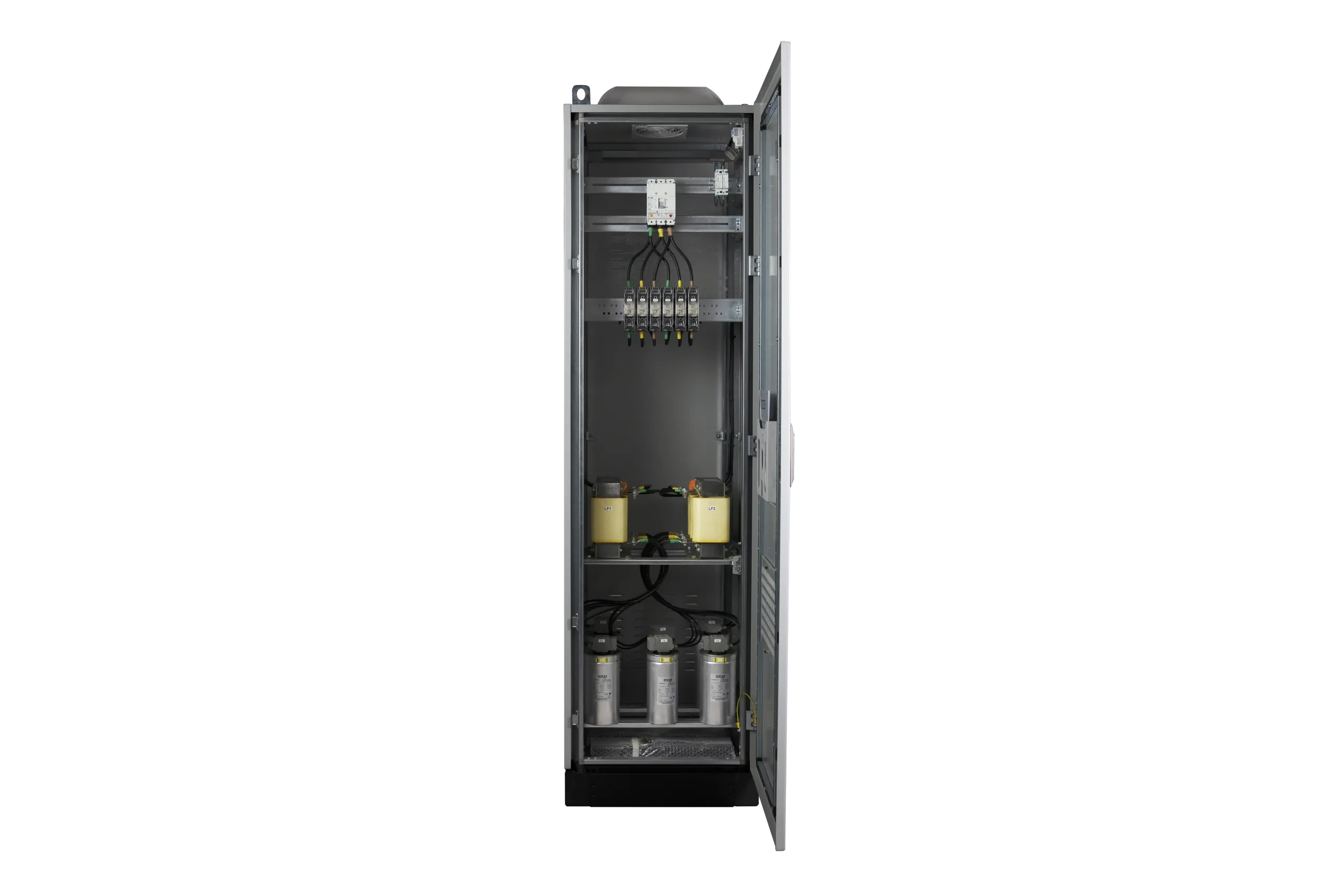
GENERAL CHARACTERISTICS
| Electrical Specifications | |
|---|---|
| Nominal voltage | 400 V – 50 Hz |
| Capacity Tolerance | -5%, +5% |
| Connection Type | Three-phase |
| Power Loss | < 7 W/kVAr for polluted network |
| Maximum Allowable Current (with thermal protection included) |
1.19 In for polluted network with a tuning factor of 3.8 1.16 In for polluted network with a tuning factor of 3.4 1.12 In for polluted network with a tuning factor of 2.7 |
| Maximum Allowable Voltage | 1.1 x Un, 8h every 24h |
| Isolation Voltage | 690 V |
| Nominal Impulse Withstand Voltage (Uimp) | 8 kV |
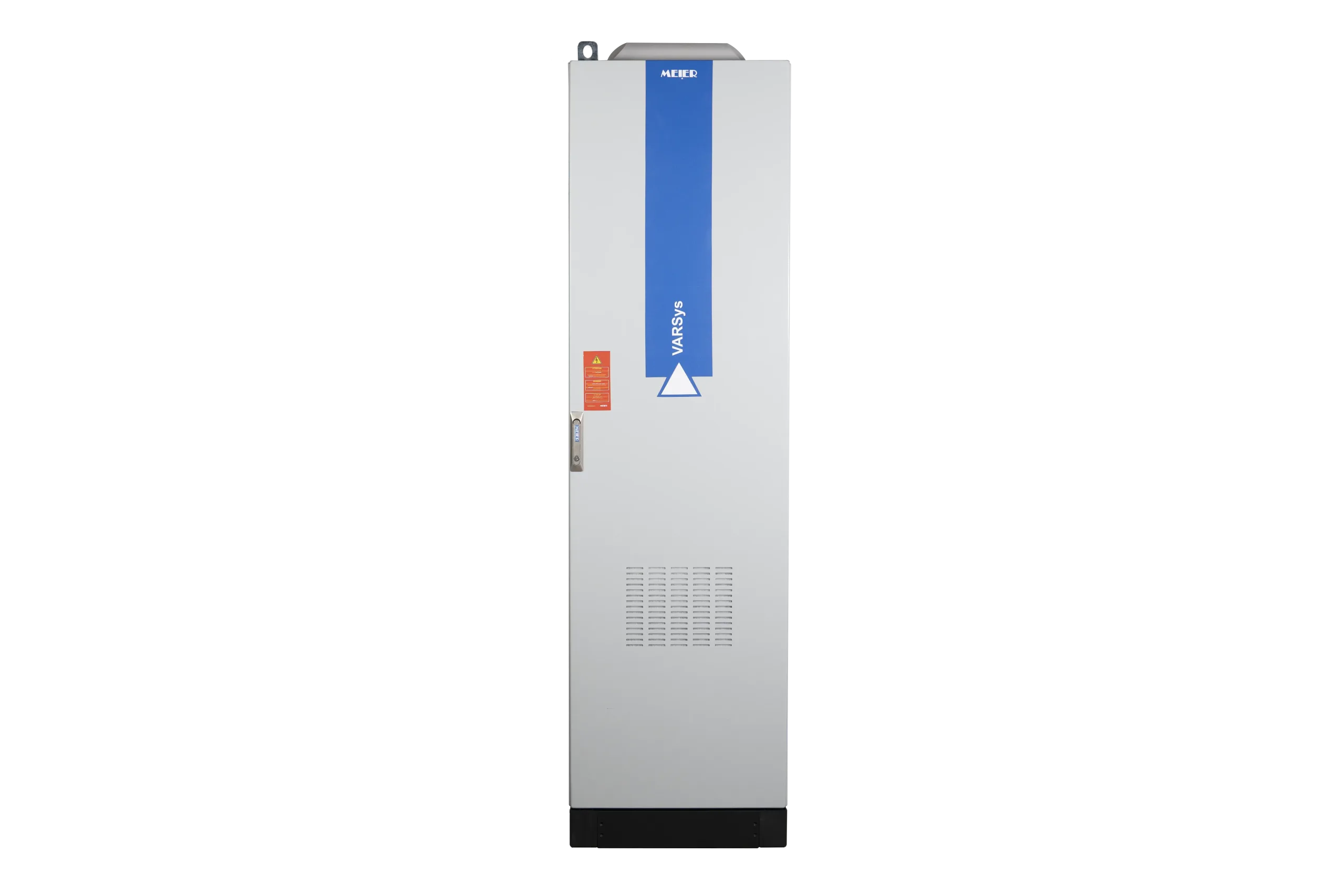
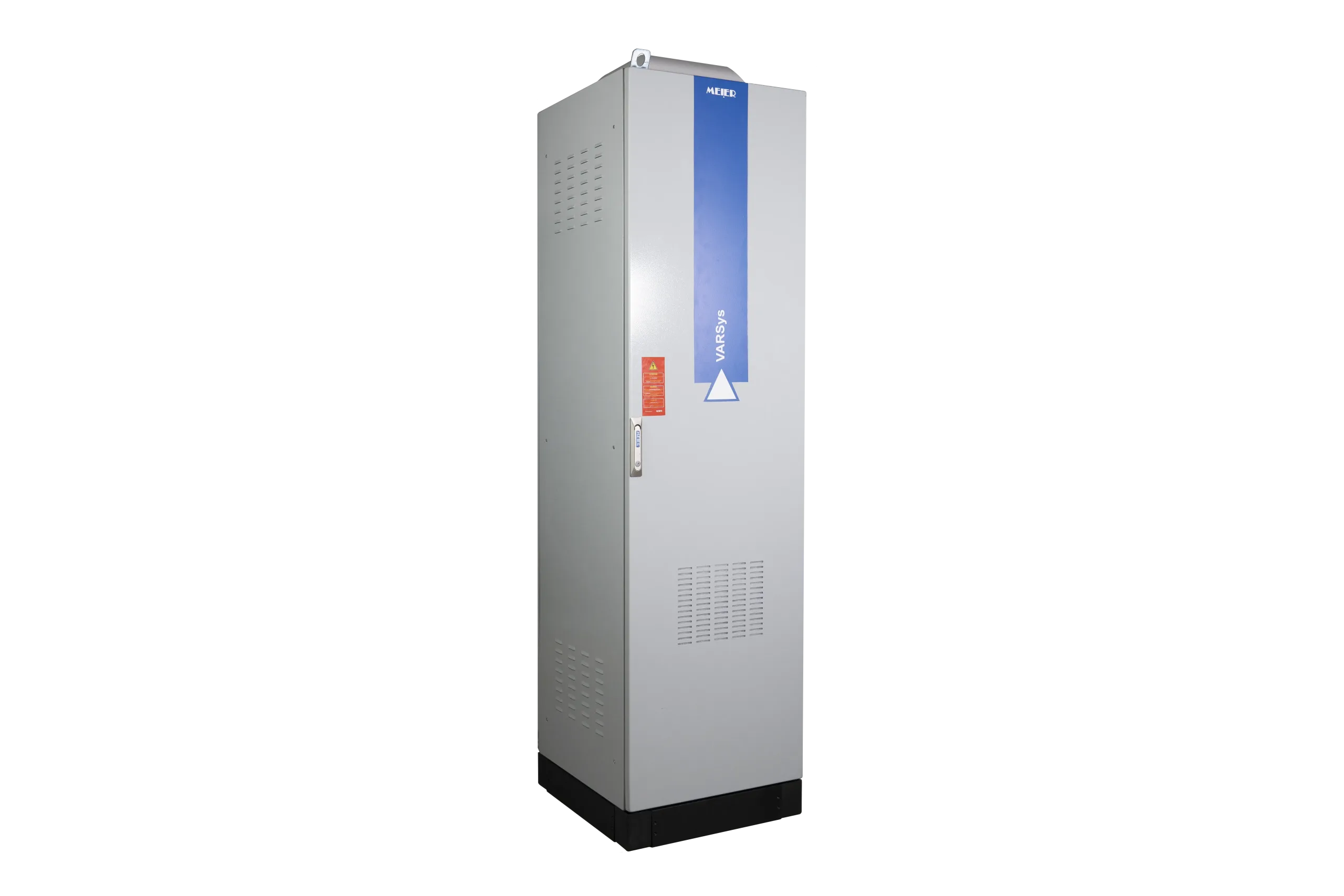
| Box | |
|---|---|
| Degree of protection | IP42 |
| Color | RAL 7035 |
| Degree of Mechanical Resistance | IK10 |
| Head Protection | |
|---|---|
| With Main Switch | Rotary Handle Switch-Disconnector The compensation bank must be protected upstream by a circuit breaker |
| With Circuit Breaker | Molded case circuit breaker Rotary handle on demand |
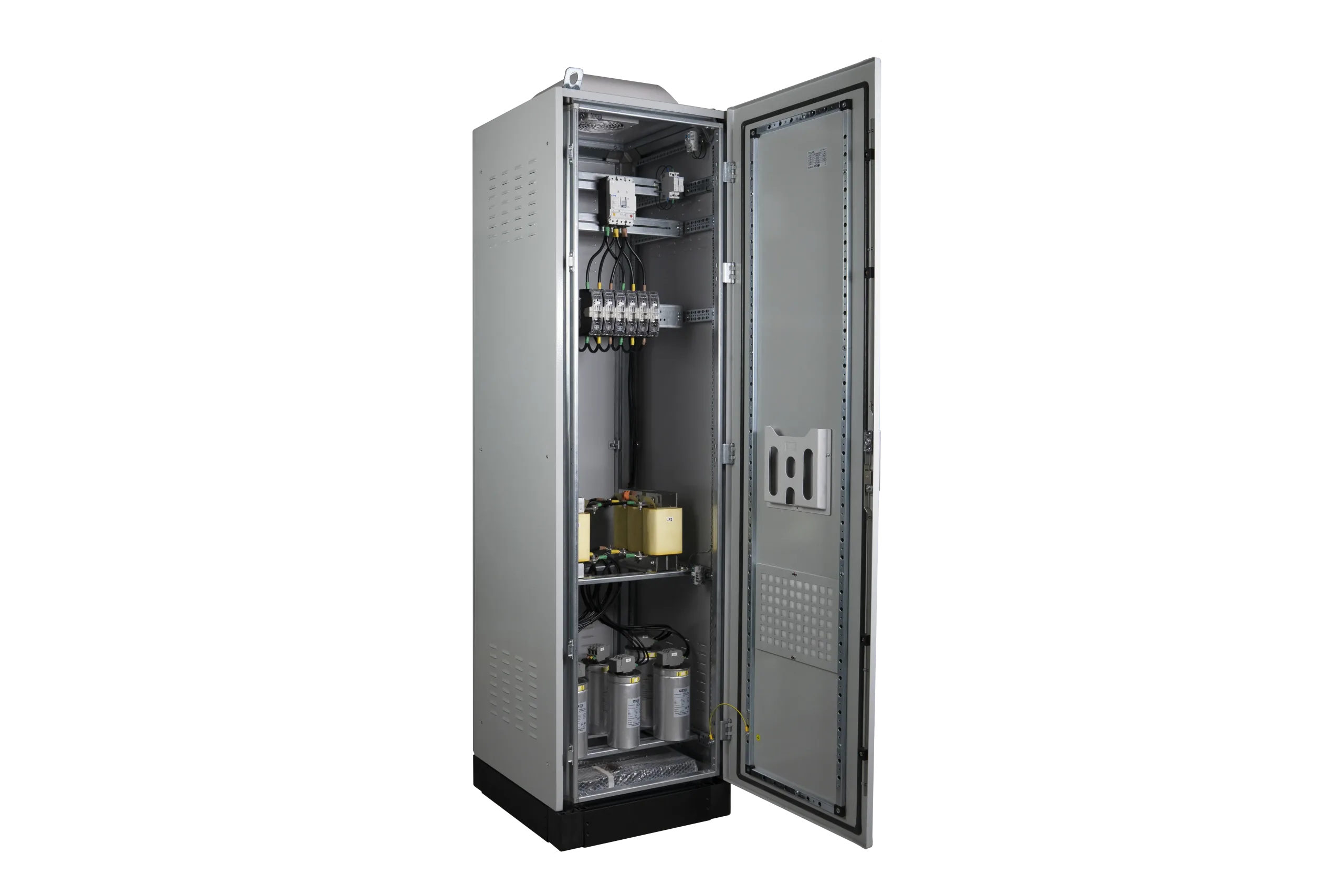
| Components | |
|---|---|
| Type of Capacitors | VARCap® 480 V – 50 Hz for polluted network with a tuning factor of 3.8 & 3.4 VARCap® 525 V – 50 Hz for polluted network with a tuning factor of 2.7 Maximum Overload: Up to 2.0 In |
| Self Anti-harmonics | VARSelf® Protection against overheating by integrated thermostat |
| Temperature Control |
|---|
| By Thermostat |
Environment
GENERAL CHARACTERISTICS
| Electrical Specifications | |
|---|---|
| Nominal voltage | 400 V – 50 Hz |
| Capacity Tolerance: | -5%, +5% |
| Connection Type: | Three-phase |
| Power Loss | < 7 W/kVAr for polluted network |
| Maximum Allowable Current (with thermal protection included) |
1.19 In for polluted network with a tuning factor of 3.8 1.16 In for polluted network with a tuning factor of 3.4 1.12 In for polluted network with a tuning factor of 2.7 |
| Maximum Allowable Voltage | 1.1 x Un, 8h every 24h |
| Isolation Voltage | 690 V |
| Nominal Impulse Withstand Voltage (Uimp) | 8 kV |
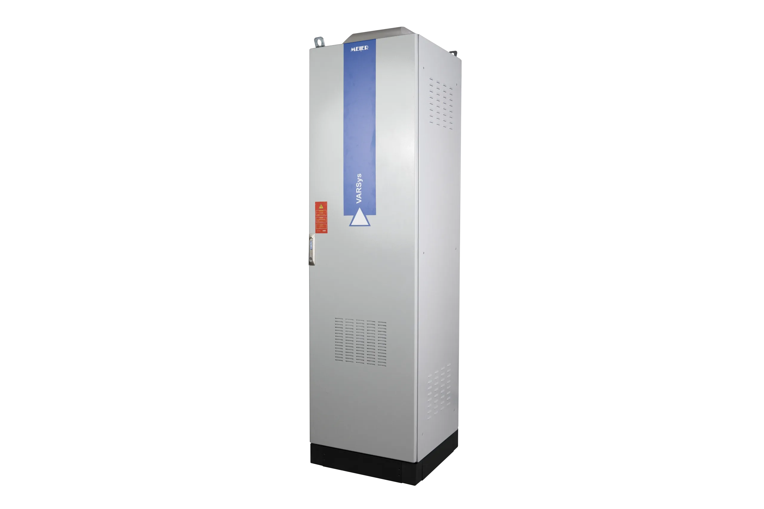
| Box | |
|---|---|
| Degree of protection | IP42 |
| Color | RAL 7035 |
| Degree of Mechanical Resistance | IK10 |
| Head Protection | |
|---|---|
| With Main Switch | Rotary Handle Switch-Disconnector The compensation bank must be protected upstream by a circuit breaker |
| With Circuit Breaker | Molded case circuit breaker Rotary handle on demand |
| Components | |
|---|---|
| Type of Capacitors | VARCap® 480 V – 50 Hz for polluted network with a tuning factor of 3.8 3.4 VARCap® 525 V – 50 Hz for polluted network with a tuning factor of 2.7 Maximum Overload: Up to 2.0 In Maximum Inrush Current: ≤500 In Operational Ambient Temperature: -40°C – +60°C Overvoltage Protection for all 3 Phases Discharge Resistance 50 V – 1 min |
| Self Anti-harmonics | VARSelf® Protection against overheating by integrated thermostat |
| Temperature Control |
|---|
| By Thermostat |