Description
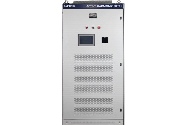
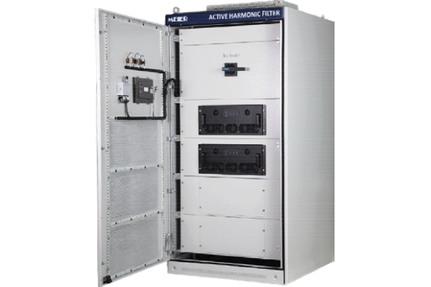
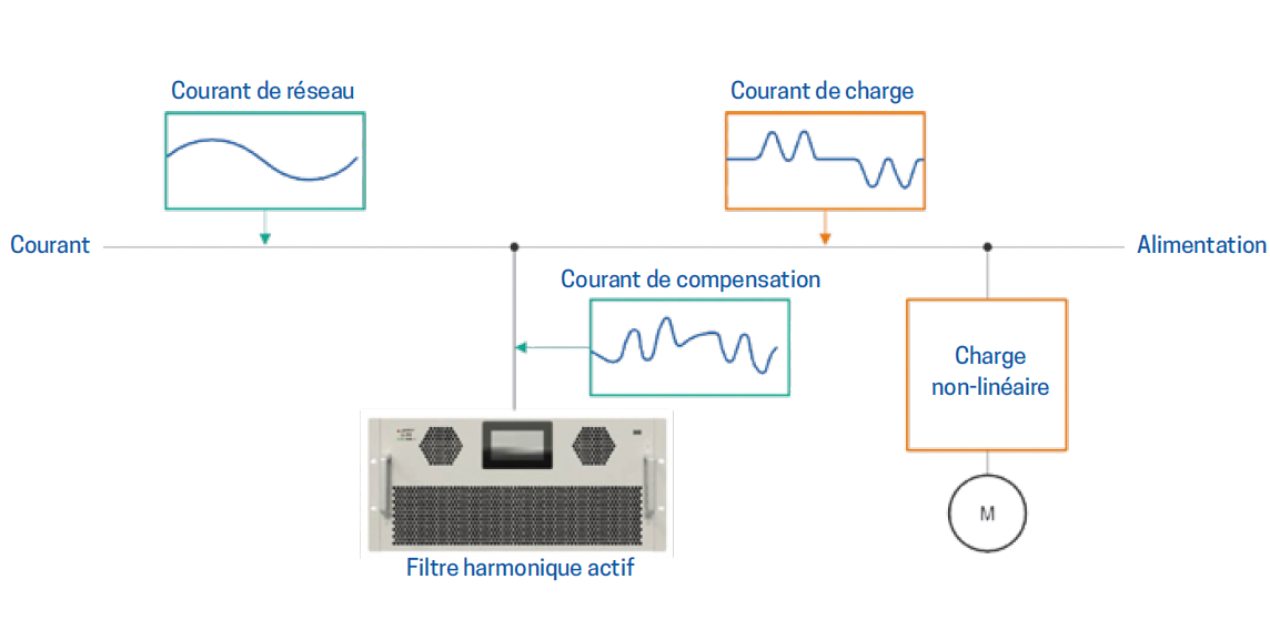
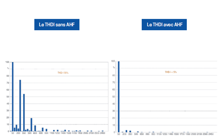
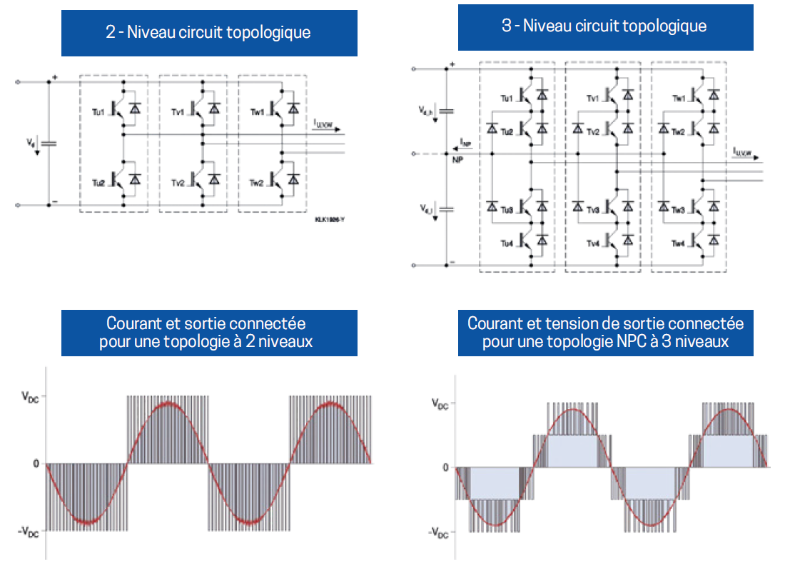
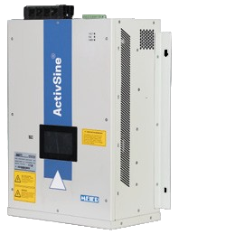
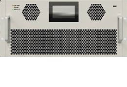
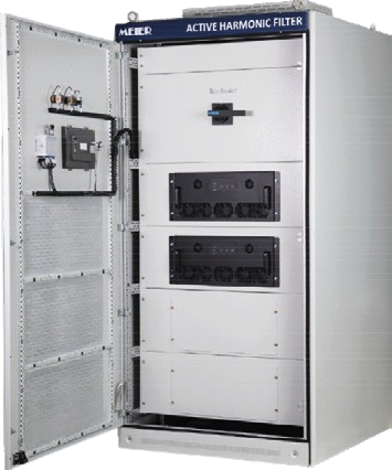
The ActivSine® series active harmonic filter operates on a three-level topology circuit. It provides power quality solutions such as harmonic elimination, real-time automatic power factor correction, and load balancing. It is available in three versions: a wall-mounted enclosure version, ranging from 30A to 150A, a rack-mountable version for standard 19” cabinets, ranging from 30A to 150A, and a cabinet version, ranging from 100A to 600A.
Its modular design allows users to easily achieve the desired filter current capacity by connecting up to 20 modules in parallel.
Wall-mounted AHF
Rack-mounted AHF
Fixed AHF cabinets
Typical applications
Safety Features
Advantages of the three-level topology:
Data and Technical Specifications:
| Wall mounting / 400V | Floor mounting / 400V | Floor mounting / 690V | |
|---|---|---|---|
| Network voltage range | -20%~+20% | -20%~+20% | -20%~+10% |
| Nominal current (A) | 30-50-75-100-150-200 | 100-200-300-400-500-600 | 100-200-300-400-500-600 |
| Frequency | 50/60Hz (-10%~+10%) | ||
| Harmonic compensation | from the 2nd to the 50th harmonic order | ||
| Harmonic compensation rate | >97%. | ||
| CT Configuration in loop | Closed or open (open loop is recommended for parallel operation) | ||
| Overall response time | 10ms | ||
| Network type | 3P3W, 3P4W | ||
| Overload capacity | 110% – Continuous operation, 120% – 1 min | ||
| Circuit topology | 3-level topology | ||
| Switching frequency | 20 kHz – Reaction time: approximately 50 ps | ||
| Modules | Up to 20 units can be combined | ||
| Redundancy configuration | Master/Master or Master/Slave | ||
| Typical power losses | 2.5% (depending on load) | ||
| Reactive power compensation | Available | ||
| Target power factor | Adjustable from -1 to 1 | ||
| Load balancing | Available (for three-phase networks with neutral 3P4W) | ||
| Display | HMI 1.8/4.3/7 inches | ||
| Communication ports | RS485 Modbus (RTU) | ||
| Noise level | <69 dB (en fonction de la charge et du modèle){{{wpml_tag_142}}} {{{wpml_tag_143}}} {{{wpml_tag_144}}} {{{wpml_tag_145}}}Utilisation en altitude{{{wpml_tag_146}}} {{{wpml_tag_147}}}>2000m | ||
| Temperature | Operating temperature: -35°C to 55°C, reduced use above 55°C Storage temperature: -45°C to 70°C |
||
| Humidity | 5%~95% RH, Noncondensing | ||
| Protection class | IP20 | ||
| Design/Approvals | EN 62477-1(2012), EN 61439-1 (2011) | ||
| EMC | EN/IEC 61000-6-4, Classe A | ||
| Certification | CE, Cmim | ||
Product Documentations
- Brochure Filtre Active d'Armoniques (FR) Download


